Get Megger Test Form in PDF
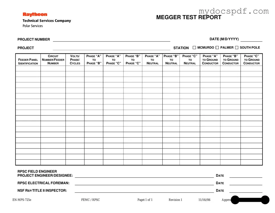
The Megger Test form serves as an essential document for recording electrical insulation resistance test results, ensuring safety and reliability in electrical systems. This form includes critical details such as the project number, project station, and the date of the test, which help in tracking and referencing the testing process. It identifies various feeder panels and circuit numbers, providing a clear overview of the specific components under evaluation. Measurements are taken between different phases and between phases and neutral or ground, including phase-to-phase and phase-to-ground readings. The form also captures the names and signatures of key personnel involved in the testing, such as the RPSC field engineer, project engineer or designee, electrical foreman, and NSF representative or inspector. By documenting these aspects, the Megger Test form plays a vital role in ensuring compliance with safety standards and facilitating effective communication among team members throughout the project lifecycle.
Dos and Don'ts
When filling out the Megger Test form, attention to detail is crucial. Here are some do's and don'ts to ensure accuracy and clarity.
- Do include the project number and station clearly at the top of the form.
- Do use the correct date format (M/D/YYYY) for consistency.
- Do identify the feeder panel and circuit number accurately.
- Do record voltage, phase, and cycles for each test conducted.
- Do ensure all measurements are taken and documented for each phase.
- Don't leave any sections blank; incomplete forms can lead to confusion.
- Don't use abbreviations that are not commonly understood.
- Don't forget to sign and date the form in the designated areas.
- Don't submit the form without double-checking for accuracy.
Document Attributes
| Fact Name | Description |
|---|---|
| Project Number | This unique identifier is essential for tracking and referencing specific projects. |
| Project Station | Indicates the location of the project, such as McMurdo, Palmer, or South Pole. |
| Date | The date of the test is recorded in the format M/D/YYYY, ensuring clarity in documentation. |
| Feeder Panel Identification | This section identifies the specific feeder panel being tested, crucial for electrical safety. |
| Circuit Number/Feeder Number | Essential for pinpointing the exact circuit or feeder involved in the testing process. |
| Voltage and Phase Details | Measurements are taken across various phases and to neutral and ground, ensuring comprehensive testing. |
| Field Engineer Signature | The RPSC Field Engineer signs off on the report, indicating responsibility for the test results. |
| Project Engineer/Designee Signature | This signature is required to validate the testing process and results, ensuring accountability. |
| NSF Representative | The NSF Rep/Title II Inspector's signature confirms compliance with relevant standards and regulations. |
Key takeaways
When filling out and using the Megger Test form, several key points should be considered to ensure accuracy and clarity in reporting.
- Project Identification: Clearly indicate the project number and station at the top of the form. This helps in organizing and tracking the test results.
- Date Entry: Always fill in the date in the format M/D/YYYY. This is crucial for maintaining a chronological record of tests.
- Feeder Panel Identification: Specify the feeder panel identification. This information is essential for identifying the electrical circuit being tested.
- Voltage and Phase Information: Accurately record the voltage, phase, and cycles. This data is critical for evaluating the electrical system's performance.
- Test Results: Document the resistance measurements between phases, neutral, and ground. Ensure that each measurement is clearly labeled to avoid confusion.
- Signatures: Obtain signatures from the RPSC field engineer, project engineer/designee, electrical foreman, and NSF representative. This adds credibility to the report.
- Review for Completeness: Before finalizing the form, review all entries for completeness and accuracy. Missing information can lead to misinterpretation of results.
- Record Keeping: Maintain a copy of the completed form for future reference. Proper documentation is vital for compliance and safety audits.
Other PDF Templates
Hazmat Bill of Lading Example - Additional charges apply if the shipment needs to be redirected.
Fedex Indirect Signature - Failure to provide a signature could result in failed delivery attempts by FedEx.
When engaging in the sale of a mobile home, it's important to have a properly structured document to protect both parties involved. The New York Mobile Home Bill of Sale form not only ensures clarity and legality in the transaction but also provides peace of mind for the buyer and seller alike. For those seeking a reliable template, you can find one at newyorkform.com/free-mobile-home-bill-of-sale-template/, which can simplify the process significantly.
Official Cuddle Buddy Application - Forge connections that enhance your emotional health.
Example - Megger Test Form
MEGGER TEST REPORT
PROJECT NUMBER
PROJECT |
|
STATION |
DATE (M/D/YYYY)
MCMURDO 
 PALMER
 SOUTH POLE
FEEDER PANEL IDENTIFICATION
CIRCUIT
NUMBER/FEEDER
NUMBER
VOLTS/
PHASE/
CYCLES
PHASE “A”
TO
PHASE “B”
PHASE “A”
TO
PHASE “C”
PHASE “B”
TO
PHASE “C”
PHASE “A”
TO
NEUTRAL
PHASE “B”
TO
NEUTRAL
PHASE “C”
TO
NEUTRAL
PHASE “A”
TO GROUND CONDUCTOR
PHASE “B”
TO GROUND CONDUCTOR
PHASE “C”
TO GROUND CONDUCTOR
RPSC FIELD ENGINEER |
|
|
|
|
|
|
PROJECT ENGINEER/DESIGNEE: |
|
|
|
|
DATE |
|
RPSC ELECTRICAL FOREMAN: |
|
|
|
|
DATE |
|
NSF REP/TITLE II INSPECTOR: |
|
|
|
|
DATE |
|
FEMC / RPSC |
Paget 1 of 1 |
Revision 1 |
11/16//06 |
Approved by Wayne L. Cornell |
||
Detailed Instructions for Writing Megger Test
Completing the Megger Test form is an essential part of documenting electrical tests for various projects. This process ensures that all necessary information is accurately recorded. Follow these steps carefully to fill out the form correctly.
- Locate the PROJECT NUMBER section at the top of the form and enter the relevant project number.
- In the PROJECT STATION field, choose from the provided options: MCMURDO, PALMER, or SOUTH POLE.
- Fill in the DATE in the format M/D/YYYY.
- Identify the FEEDER PANEL IDENTIFICATION and input the appropriate details.
- Next, enter the CIRCUIT NUMBER/FEEDER NUMBER as required.
- In the VOLTS/PHASE/CYCLES section, provide the necessary voltage and cycle information.
- For the next fields, measure and input the resistance values for the following pairs:
- PHASE “A” TO PHASE “B”
- PHASE “A” TO PHASE “C”
- PHASE “B” TO PHASE “C”
- PHASE “A” TO NEUTRAL
- PHASE “B” TO NEUTRAL
- PHASE “C” TO NEUTRAL
- PHASE “A” TO GROUND
- PHASE “B” TO GROUND
- PHASE “C” TO GROUND
- Next, locate the RPSC FIELD ENGINEER section and write the name of the engineer responsible for the test.
- In the PROJECT ENGINEER/DESIGNEE section, enter the name and date of the project engineer or designee.
- Fill out the RPSC ELECTRICAL FOREMAN section with the foreman's name and date.
- Finally, complete the NSF REP/TITLE II INSPECTOR section by providing the inspector’s name and date.
Once you have completed the form, review all entries for accuracy. This careful attention to detail helps ensure that the testing process is well-documented and reliable.
Documents used along the form
The Megger Test form is an essential document used to record the results of insulation resistance testing. However, it is often accompanied by other important forms and documents that provide additional context, support, and compliance for electrical projects. Below is a list of commonly used documents that complement the Megger Test form.
- Electrical Inspection Report: This document details the findings of a thorough inspection of electrical systems. It helps ensure compliance with safety standards and regulations.
- Maintenance Log: A record of all maintenance activities performed on electrical equipment. This log is vital for tracking performance and scheduling future maintenance.
- Test Equipment Calibration Certificate: This certificate verifies that the testing equipment used, such as the Megger, has been calibrated according to industry standards. It ensures the accuracy of test results.
- Installation Verification Form: This form confirms that electrical installations have been completed according to design specifications and safety codes. It is crucial for project acceptance.
- Safety Compliance Checklist: A checklist that outlines safety protocols and procedures that must be followed during electrical work. It helps prevent accidents and injuries on-site.
- Project Change Order: A document that outlines any changes made to the original project scope, including modifications to electrical systems. It is important for maintaining project clarity and accountability.
- Site Assessment Report: This report evaluates the conditions of the work site before any electrical work begins. It identifies potential hazards and ensures proper planning.
- Quitclaim Deed Form: This legal document allows for the transfer of property interest without title guarantees, often used in personal transactions. For more details, refer to NY Templates.
- Final Project Report: A comprehensive summary of the entire project, including challenges faced, solutions implemented, and overall outcomes. It serves as a reference for future projects.
- Training Records: Documentation of training sessions attended by personnel involved in electrical work. It ensures that staff are adequately trained in safety and operational procedures.
These documents work together to create a comprehensive framework for managing electrical projects. Each plays a crucial role in ensuring safety, compliance, and efficiency throughout the testing and installation processes.